| |
Fluid Motion
Many times the objective is to provide a pumping action throughout the tank. The pumping capacity of impellers can be measured by photographic techniques, hot wire or hot film velocity meters, or laser doppler velocity meters. There is no generally agreed upon definition of the discharge areas for impellers, so that the primary pumping capacity of mixing impellers varies somewhat, depending on the definition used for discharge area. There is considerable entrainment of fluid in the tank, due to the jet action of the flow from the impeller. At about 0.6 DIT ratio further increases in total flow in the tank are difficult to achieve, since there is no more entraining action of the impeller in the total system.
The pumping capacity of a mixing impeller is specified by either the flow from the impeller or the total flow of the tank. Flow varies for any
impeller as the speed and diameter cubed. Q = KND3 and k is factor for various impeller types. The radial flow impeller has essentially less flow and higher shear rates than does the axial flow impeller type.
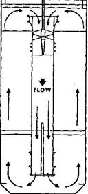
If the impeller is required to pump against a static head or a friction head within the channel of the mixing tank, then there must be a series of head flow curves developed for the impeller being used. This is a function of the clearance between a radial impeller and a horizontal baffle. The hole in it allows the flow to come into the impeller zone but not circulate back, or the clearance of an axial impeller in a draft tube. The operating point, then, will be the intersection of the impeller head flow curve and the system head flow curve. Draft tube circulators have the advantage of giving the highest flow in the annulus for a given level of power or requiring the least power to provide a given flow of the annulus. When pumping down the draft tube, the flow in the annulus must equal the settling velocity of the particles, and the total flow can be calculated on that basis. In practice, the flow coming up the annulus is not a uniform flat velocity profile, so that additional total flow is needed because of the nonuniform distribution of the upward axial velocity to the annulus. Pumping down the draft tube allows the tank bottom to be flat or have very small conical fillets at the sidewalls.
Pumping up the draft tube requires that the solids are to be suspended in the draft tube with a much lower total flow, and also power, and then make their own way down the outside of the annulus coming into the bottom of the draft tube again. This means that the bottom of thetank must usually have a steep cone, and suitable flares and baffles must be added to the draft tube bottom so that the flow comes up in a uniform fashion for proper efficiency.
 Draft Tube - Will discussed further in the Industrial Section. Draft Tube - Will discussed further in the Industrial Section.
When using a draft tube, the back flow possibility in the center of the impeller requires the use of a large-diameter hub. This is not normally desirable in fluidfoil impellers used in open tanks. The system head for a draft tube circulator is a function primarily of the design of the entrance and exit of the draft tube, and considerable work has been done on the proper design and flaring of these tubes for special applications.
The main use of draft tube circulators has been in precipitators and crystallizers. A further requirement is that the liquid level be relatively uniform in depth above the top of the draft tube, which means that variable liquid levels are not practical with draft tube systems. In addition, slots are often provided at the bottom of the draft tube, so that should a power failure occur and solids settle at the bottom of the tank, flow can be passed through these slots and scrub out particles at the bottom of the tank for resuspension
|