Side Entry Blending
A stratified, unblended, tank consists of a series of strata, or layers of fluids.
The process of blending requires breaking down the interfaces between the various layers. The interface between adjacent layers is a physical barrier, one that requires energy to destroy. When a stream with
a low energy level encounters such an interface, the stream is contained almost as effectively as if the interface were a tank wall.
It is necessary to break down the interface by erosion, or "turbulent entrainment".
A mixing impeller blends by producing flow in the zone around it and entraining additional fluid into the moving, turbulent stream. In low
viscosity systems, there is enough turbulence that once fluid is put into motion, uniformity is achieved very rapidly. The mixer then applies the
energy of the fluid stream to the interface of the stratified layer above, breaking through the interface or wearing it away, to bring that fluid into motion. Power input determines the energy level in the flowing stream,
thus determining the length of time that will be required to blend to uniformity.
In other words, blending is accomplished by entrainment. The fluid stream from the propeller is essentially a large jet which adds to its volume by entraining additional fluid from the surroundiing quiet zone. Just as a 420 RPM propeller mixer is more effective than the small, high velocity
jet from a nozzle, so the 280 RPM propeller is more effective than the high speed propeller. So it is with any type of mixing impeller - propeller, turbine or paddle.
Higher pumping capacity puts more fluid in motion by direct action of the impeller and gives the lower-speed unit a "head start" on the entrainment operation.
As with all good things, the entrainment will eventually come to an end. Since energy is required to bring in new fluid, the fluid stream will eventually reach the point (if the tank is large enough) where turbulence at the active/quiet surface will not be equal to the task of entrainment. Then time will be required for the system to build up momentum, progressively wear away the interface until the moving stream reaches the liquid surface and the entire tank is in motion.
This flow pattern is particularly notable in petroleum installations where the power input for the total volume to be handled is relatively low. This action usually takes place much more rapidly in small tanks with higher input, to the point that the erosion mechanism may be hardly recognizable. Where the energy input is high enough that the flow to the surface is produced immediately, the blending time, with low viscosity fluids, is normally a matter of minutes. With higher viscosity fluids, or with a wide spread in viscosity, the turbulence produced by flow alone may not be sufficient to blend rapidly, therefore additional time should be allowed to carry out the "dissolving" of one liquid into the other.
The key factors in considering any blending job are:
1. Mixer Input
2. Blending Time Requirement
3. Fluid Properties:
- Viscosity (Components and Final Blend)
- Densities
- Density Differences
4. Operating Procedure:
- Stratified Condition
- Mixer Running Time during Completion of Pump-up
All of these factors are used to determine the mixer requirement for a
process job. Operating methods, suggested to enhance the capacity of the mixer, are just as much a part of the recommendation as the mixer specification and should be included and emphasized.
Horsepower, D/T, and impeller characteristics define the mixer input in any system. Process result is specified in terms of the time allowed to
bring about uniformity. The viscosity, densities, and the density difference between components control the level of power input required. When all components are low viscosity, as in gasoline, light oils, and many aqueous solutions, the relative difficutly of blending is a function of the difference in densities between stratified layers.
As the density difference increases, the difficulty of blending increases, therefore, more power or flow is required in the system.
Operating the mixer during the filling of a tank eliminates the problem
of stratification and allows mixing at much lower power levels. Injection of a lighter or heavier fluid into the general flow pattern produces rapid blending and only a short additional mixer time is required after all components are added. While it is not always possible to add all components in a short time with the mixer operating, substantial savings can be made.
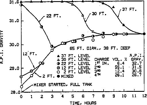
Above is an example of stratified 20,000 barrel tank of furnace oil using a 10 HP side entry mixer. After 12 hours have uniformity - no stratification of products.
Side Entry Blending Selection Guidelines
Initially Side entry was heavily used in various Pulp and Paper applications as well as Oil Blending and over time it has taken on popularity in the chemical industry such as for storage tanks.
Keep in mind when comparing with a top entry unit the side entry mixers require 2 to 3 times more HP to achieve the same mixing however they are significantly lower in capital cost.
The sizing procedure recognizes the tank mixing blend time is related directly to impeller pumping capacity. The liquid level to tank diamater ratio (Z/T limits) have been quantified and it shows that relatively tall tanks can be blended without difficulty. The Reynolds number becomes a prominent factor in moderate viscosity blending. All of these factors are combined to provide a reliable sizing procedure for which the blend time can be guaranteed. It provides a definitive mixer size for general chemicals industry blending applications.
Blend Time (mins.)= 630 (Volume in gallons) (Viscosity factor) (N.. factor) (Z/T factor) / ( N D^3)
Blend time, in minutes, is defined as the length of time needed to blend a component into an unstratified tank. The blend time calculation also assumes that additional feed streams will not stratify.
Volume is the maximum batch size in U.S. gallons.
Viscosity factor is empirical (contact ZAIN) This factor takes into account the increased viscous drag at the tank wall at increased viscosities.
Reynolds number factor is empirical (contact ZAIN). This factor takes into account both changes in impeller pumping characteristics and flow discharge angle that occur in the transition region (300 < Reynolds Number < 3000). This factor is 1.0 when Reynolds Number > 3000.
Z/T factor. Z/T factor will be 1.0 for all acceptable Z/T. Contact ZAIN for Z/T limits.
Z/T limits. This procedure is recommended when Z/T < 2.5. In water-like fluids the Z/T limit may be higher, but has not been quantified. Minimum Z/T is controlled by having liquid coverage over the impeller and minimum Z/T of 0.25.
SIDE ENTRY MIXER SIZING — BLENDING
CHART (AT Z/T=1.0) High Flow impeller at 280 RPM {* HorsePower / * Blend time in minutes)
FINAL
VISCOSITY (Cps)
|
VOLUME (USGAL) |
5,000 |
10,000 |
25,000
|
50,000 |
100,000 |
250,000 |
500,000 |
1 |
*1 / *3 |
2 / 5 |
3 / 6 |
5 /
10 |
10 / 12 |
20 / 25 |
30/ 30 |
100 |
1 /
12 . |
2 /
20 |
3 /
25 |
7.5 /
30 |
15 / 40 |
25 / 70 |
40 / 110 |
250 |
2 /
13 |
3 /
15 |
5 /
25 |
10 / 30 |
20 / 40 |
30 / 85 |
50 / 120 |
500 |
2 /
17 |
3 /
20 |
7.5 / 30 |
15 / 40 |
25 / 55 |
40 / 100 |
60 / 160 |
1000 |
3 /
25 |
5 /
30 |
10 / 40 |
20 / 45 |
30 / 70 |
50 / 120 |
|
2500 |
5 /
40 |
7.5 / 55 |
15 / 85 |
25 / 95 |
40 / 130 |
60 / 240 |
|
5000 |
7.5 / 55 |
10 / 75 |
20 / 110 |
40 / 140 |
60 / 190 |
|
|
|